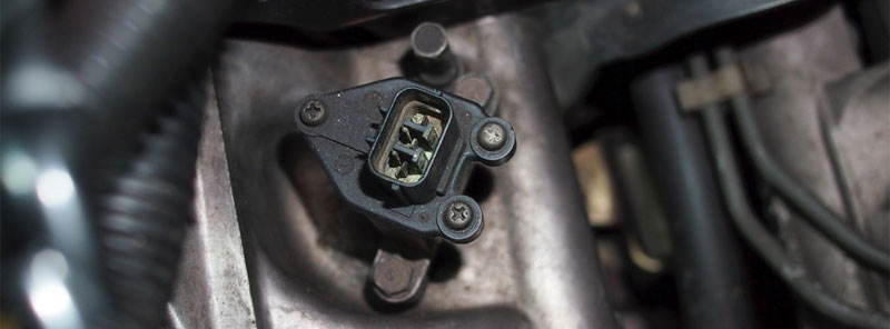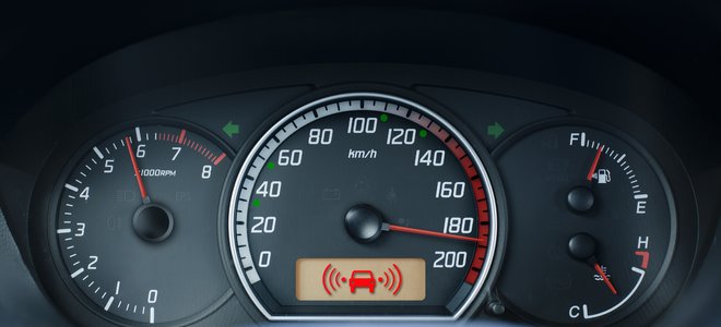
The vehicle speed sensor (VSS) is the crucial component of the automotive electronic control system. The sensor converts the vehicle speed data into electrical signals while driving and transmits them to the electronic control unit.
This process controls other functions such as engine idling speed, automatic transmission torque converter locking, automatic transmission gear shifting and cruise control. The VSS keeps the vehicle in the best working state.
The speedometer measures and displays the instantaneous speed of a vehicle. In simple terms, a system within the speedometer (contains a turntable with a pointer shaft, a spindle with a permanent magnet, bearings, hairsprings) controls the pointer's swing.
The output rotational speed of the transmission determines the swing amplitude of the pointer. The flexible shaft, which connects to a worm gear on the output shaft of the vehicle transmission or distributor, drives the speedometer.
There are assembly errors, natural wear and tear in the manufacturing and usage. These factors cause deviation in the speedometer indication.
The vehicle speed sensor installs next to the output shaft of the gearbox. Another one installs on the odometer for the auxiliary transmission, which acts as insurance against failure when the former one fails.
Vintage sensors mainly measure the rotational speed of the transmission shaft. They link to the transmission shaft and transmit information to the speedometer by a flexible shaft. The speedometer shows the instantaneous speed.
Nowadays, electronic sensors are widespread. They locate in the same place. But instead of using a flexible shaft, they use wires to transmit the speed signal to the speedometer. If we drive over the speed limit, the warning light on the dashboard will remind us.
The vehicle speed sensor usually installs in the drive axle housing or transmission housing. The speed sensor signal line usually installs in a shield to eliminat agnetic and radio frequency interference generated by high voltage electrical wires, car phones, and other electronic equipment. The guard ensures that electronic communication doesn't produce interruptions. It prevents poor driving performance or other problems.
In Europe, North America and Asia, magnetoelectric sensors are widespread in various vehicles to control vehicle speed, crankshaft angle and camshaft angle. Furthermore, the sensor detects the speed and location of other rotating parts, such as the compressor clutch.
(1) The sensor weighs 2kg. Fix the sensor by clip to the sheath of the load cable (the cable that sends to the load from the switch outlet nozzle). After selecting a good location, compress the top bar on the clip and mark it.
To prevent movement during working, the clip should be in a place where it doesn't move (for example, the cable suspended from the wall). However, it is crucial to avoid alternating magnetic fields, which prevents misjudgments.
(2) Electrical wiring: The sensor has two nozzles. One is the DC power inlet nozzle; the other is the polarity constant outlet nozzle. Both are spark-safe inlet and outlet nozzles.
Anode and cathode poles of the input power supply connect to the anode and cathode of the intrinsically safe power supply. Two constant current output terminals of the sensor connect to the substation.
(3) Adjustment: Put the sensor detection coil near the energized load cable. The green light of the LED should be on. Shift the sensor to the left and right along the cable.
If the green light is off and the red light is on, then find out the location of the red light on both sides and take the middle place and fix the sensor.

If the green light stays on during the shift, the reasons probably are:
① The load in the tested cable is so high, or the cable shielding is so low that the magnetic field around the cable is powerful. The solution is to adjust the resistance of the potentiometer W1 on the circuit board. Then repeat the shift on the cable to find the best fix position.
② The strong magnetic field exists. Try to avoid it appropriately.
③ The installation location is close to other strong signal supply cables, which causes interference. Try to avoid other adjacent cables.
If the red light stays on during the shift, the reasons probably are:
① The measured cable isn't charged with electricity. The adjustment must go on with electricity.
② The cable load under test is so small, or the cable shield is so large that the surrounding magnetic field is minimal. Turn up the resistance value of W1. Increase the magnification and then fix the sensor again.
The fixed sensor needs repeatedly on/off switching to check the green/red light condition. After everything is fine, mark the place on the cable. The place can't be somewhere people easily touch. The movement of the sensor affects the detection.
Adjustment of the constant current output: With the green (or red) light on, connect a DC ammeter in series with the constant current signal transmission line and adjust potentiometer W2 so that the output DC is 5±0.5 mA. After the adjustment, the sensor automatically goes into service.
(1) Check if the sensor tip is dirty.
(2) Check if the gap between the sensor head and the gear ring follows the rules.
(3) Check if the gear ring is defective.
(4) Check if the resistance value of the solenoid coil follows the rules.
There are two possible failures:
① The vehicle speed sensor fails.
② The speedometer signal processing module fails.
The vehicle speed sensor provides the speed signal to the speedometer. The meter sends the information to the ECU. So see if the speed signal from the meter makes sense. If the speed signal is correct, but the ECU still reports failure, it could be a problem with the meter.

When the vehicle speed sensor fails, the unstable engine idle speed annoys us. When the car starts the engine or decelerates to a stop during driving, momentary standstill and stalling happen. The performance of the engine acceleration reduces.
Solution: The vehicle speed sensor frequently fails. If it's a problem with the sensor itself, replace it. If the sensor is qualified, check the signal generator that works with the sensor to solve the issue completely.
For more expert tips, advice on various types of sensors, take a look at our other articles here on the Delcoribo blog.
 Lauritz Carolsfeld
  June 28, 2021
